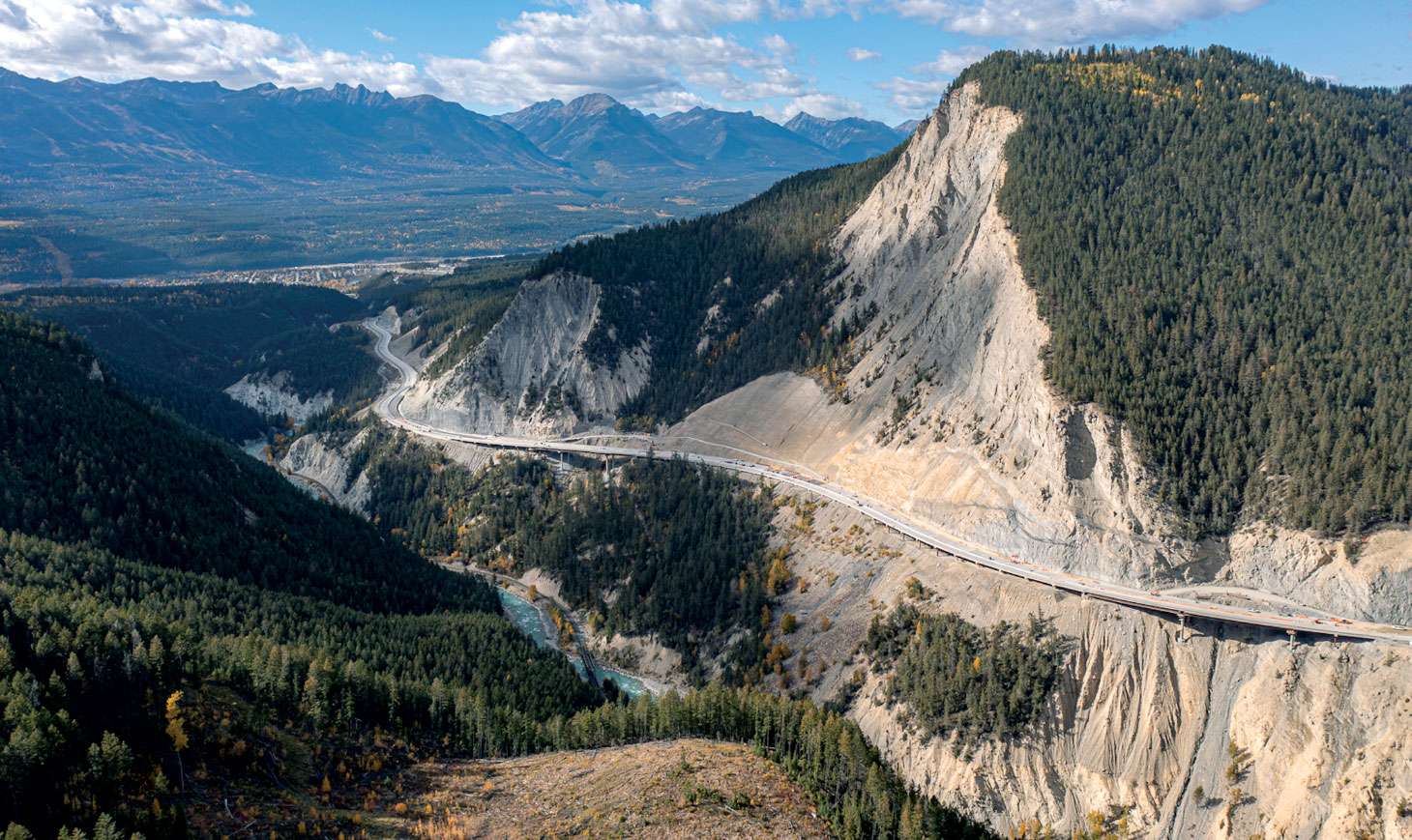
Located just east of Golden, B.C., the Kicking Horse Canyon is among the most rugged and picturesque regions along the Trans-Canada Highway. During the busy summer tourist season, this important section of highway sees more than 10,000 vehicles every day and is a critical link for both interprovincial and international trade.
In 2003, Phase 1 of the Kicking Horse Canyon project commenced with the construction of the Yoho Bridge, kicking off more than 20 years of highway rehabilitation that has seen 21 kilometres of narrow, winding two-lane highway transformed into a modern four-lane, 100 kilometre per hour standard. Part of the comprehensive Highway 1 – Kamloops to Alberta – Four Laning Program, this project will allow traffic to move more efficiently, as well as connect communities better than ever before.
Phase 4 (Canyon) of the Kicking Horse Canyon project is located on the section of highway between the previously completed Phase 3 West (Golden Hill to West Portal) and Phase 1 (Yoho Bridge) sections. Phase 4 caps off the last – and most challenging – 4.8 kilometres of the project to date.
With major construction commencing in 2021 and completed in November 2023, the work on Phase 4 included the realignment of 13 curves and a widening of the highway to four lanes with a median barrier, as well as wider shoulders to accommodate cyclists; the addition of catchment ditches and other measures to help mitigate rock fall and avalanche hazards; and the installation of wildlife exclusion fencing and wildlife passage opportunities to help reduce vehicle–animal collisions.
“Highway 1 through the Kicking Horse Canyon is a key gateway for goods and travel between British Columbia and the rest of Canada and, at the same time, it was also seen as the most treacherous section of the Trans-Canada Highway,” said Bruce Hamersley, P.Eng., FEC., president and principal engineer at BASIS Engineering Ltd.
“There was a high accident rate due to roadway geometry deficiencies, rockfall and other geohazards, as well as inadequate roadway shoulders and barriers. Four laning and safety enhancements have allowed for an increase in reliability and the volume of goods flowing west from British Columbia, and the project has achieved a significant improvement in public safety.”

A collaborative effort
This project was a demonstration that it takes many hands to move mountains. Transportation Investment Corporation is delivering the project on behalf of the Ministry of Transportation and Infrastructure, with funding provided by both the provincial and federal governments. The contractor for the project was Kicking Horse Canyon Constructors, which was a joint venture between Aecon, Parsons and Emil Anderson Construction, with Parsons providing roadway, drainage and utilities engineering on the project.
Thurber Engineering was the lead geotechnical engineer on site and was responsible for geotechnical engineering on the western two-thirds of the project, as well as carrying project-wide responsibility for rockfall and debris flow mitigation. Thurber worked alongside BASIS to develop design methodologies for viaducts and bridges, which considered unique loading scenarios from moving foundation soils due to soil retrogression and active landslides. BASIS (Bridge and Soils Integrated Solutions) is a multidisciplinary consulting firm headquartered in Burnaby, B.C., that specializes in providing bridge, structural and geotechnical engineering services.
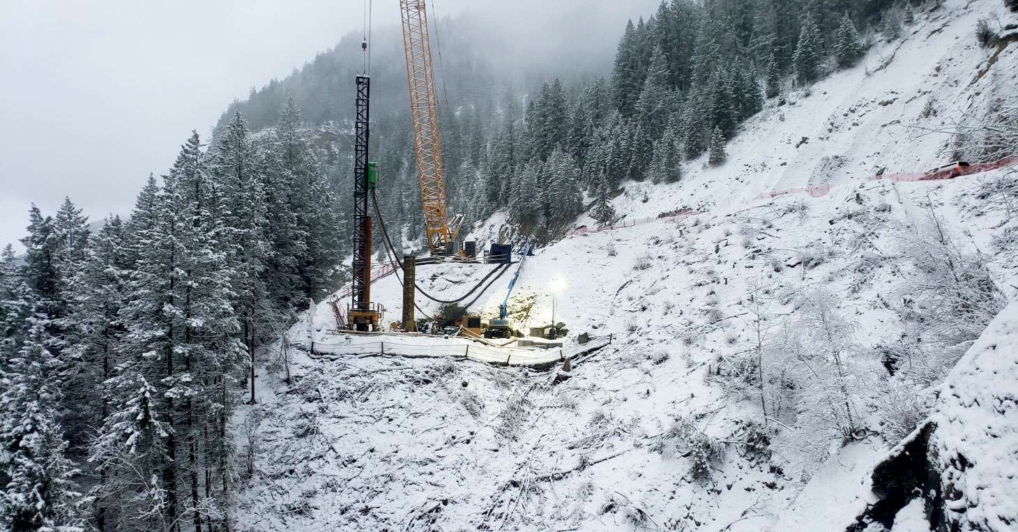
On Phase 4, BASIS brought all its expertise to the table to provide the structural design for nine viaduct bridges and three major retaining walls, as well as geotechnical engineering for the eastern third of the project. This project was also made more challenging by the need to maintain traffic through the narrow, steep corridor during the construction period (albeit slowed to 50 kilometres per hour), which required numerous temporary supports and stabilization for crane pads and pile drilling equipment access.
Given the high alpine terrain and variable weather conditions, maintaining a safe worksite was paramount throughout the course of the project.
“Most of the work BASIS does is on design-build transportation projects, and we are best known for our work on challenging soil structure interaction problems,” said Hamersley. “There were unique loading requirements for the bridge foundations due to the variety of geohazards including downslope soil retrogression, active landslides, rockfall, debris flows and avalanches. The other phases of the project might have dealt with one or two of those loading requirements, but never all of them at once. This was also the steepest section, so the temporary works designs were much more challenging to pull off.”
Construction Drilling (CDI) performed most of the piling works and Pacific Ground Engineering installed the micropiles.
The piling scope
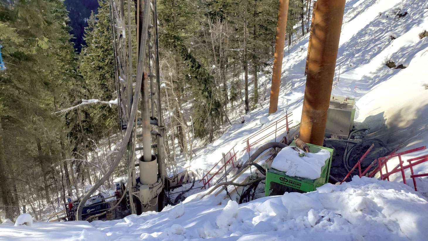
There was a wide array of piling equipment used on site to construct the rock socketed piles. The different piling methods included a crane-suspended dual rotary system with casing rotator, which was effective when installing casing through overburden and embedding casing into rock; a 230-ton crawler crane with kicker and downhole hammer, which was able to advance the casing with the downhole hammer without the need for a casing rotator; a dual rotary Barber DR40 Rig rotary that was effective when installing casing through overburden and embedding casing into rock, but no crane requirement; a Soilmec SR-95 drill rig, a track-mounted hydraulic rotary rig that came in handy when piles could be reached from the existing highway; and – last but not least – a Klemm ODEX hammer micropiling rig.

The viaduct piles utilized drilled shafts with rock sockets for the axial resistance and, where stability piles were required, the design called for casing embedment into rock or drilled to an elevation to gain the lateral resistance. The viaduct piles were connected to the precast pile cap using a smaller diameter pipe section, which was embedded in concrete at both ends and used welded rings for load transfer without internal reinforcing cages.
The pile sizes included: ASTM A252 GR.3 steel casing (with a 914-millimetre outer diameter and 19-millimetre wall thickness, and welded teeth protruding 19 millimetres beyond the outer casing) and ASTM A252 GR.3 steel casing (with a 1.292-millimetre outer diameter and 19-millimetre wall thickness). Micropiles were used in areas where access was restricted. The micropiles required 273-millimetre and 219-millimetre outer diameters, and 12.7-millimetre-thick steel casing. Rock sockets were up to 12.5 metres long.
Sustainability and safety kept top of mind
To maintain the pristine beauty of the canyon and mitigate the impact of the project, CDI used reverse circulation drilling. Reverse circulation is proven to be a cleaner and more environmentally friendly method of deep foundation installation that provides a continuous path for the drill tailings to be transported from the bit face to the surface. All cuttings that were brought to the surface by high pressure air were then carried directly into the tailings containment bin, which was continuously emptied to avoid overfilling. The cuttings were ultimately disposed of off-site.
“Then, to mitigate water breakdown during the initial stages of piling, the initial pile embedment was performed using the rotator,” said Hamersley. “Here, the casing was rotated into the ground as far as possible before engaging the downhole hammer and, once water was introduced into the system using the downhole hammer, the majority of the water ended up in the tailings bin. Packer rubbers were also utilized as containment measures around the bin.”
Given the high alpine terrain and variable weather conditions, maintaining a safe worksite was paramount throughout the course of the project. Safe work was ensured through rigorous safety checks every morning in the form of safety meetings, equipment inspections, start cards and walkovers prior to piling.
A challenging project
Already working in rugged and difficult terrain and alongside an active highway, there were also several significant challenges for the team to overcome specific to the installation of the viaduct and micropiles.
“There were unique loading requirements for the bridge foundations due to the variety of geohazards including downslope soil retrogression, active landslides, rockfall, debris flows and avalanches. The other phases of the project might have dealt with one or two of those loading requirements, but never all of them at once.”
Bruce Hamersley, P.Eng., FEC., BASIS Engineering Ltd.
“All piles were to be installed on the downslope of the existing highway, which was heavily vegetated and with slopes steeper than 1H:1V – where the proportion of the height of the rise is higher than the length of the slope,” said Hamersley. “As a result, the geotechnical, construction and piling teams were required to cut temporary access roads and create crane/rotator pads that were wide enough to conduct the works, but also had adequate bearing capacity to support the piling equipment.”
Another challenge the piling team faced was the presence of quartzite boulders within the overburden. The downhole hammer and casing installation struggled to advance through these boulders and often the teeth on the casing were destroyed, which meant that casings either had to be pulled back and the teeth replaced, or significant time needed to be spent hammering through the quartzite boulders.
The geotechnical and piling team also faced challenges associated with identifying the top of rock confirming the condition of the rock sockets. The geological conditions were such that there was bedrock-derived glacial till overlying the bedrock, resulting in the downhole hammer cuttings for these two geological units appearing similar. Because of this, after the field engineer had interpreted the top of rock and the rock socket was formed, each pile was sounded and filmed with a downhole camera to visualize the rock socket condition.
“This project represents what can be achieved within a three-year period with over 500 piles being installed,” said Hamersley. “One of the major lessons learned was that, for rock socketed piles, having the ability to film the sockets gave significant confidence to the design when in complex geological environments.”