
Axial static load tests (top-loaded and bi-directional compression, and tension) have an important role in design and construction of all deep foundation types: driven piles, augered cast-in-place piles, drilled displacement piles, helical piles, drilled shafts, etc. (all referred to herein as piles). The usefulness of static load tests, particularly in the design phase, is greatly enhanced by determining load-transfer response.
Load-transfer response refers to how the surrounding geomaterial causes changes in internal axial pile forces, mobilizing shaft resistance and end bearing, both as a result of relative pile-soil movement (t-z, and Q-z and/or q-z relationships, respectively). The objective of an instrumented static load test is to determine mobilized shaft resistance forces based on calculated internal pile forces.
Load-transfer measurements are commonly obtained using strain gauges installed at various locations along the pile. The reliability of strain measurements may be excellent, but converting strain measurements to calculate internal forces is not straightforward, as it depends on the pile’s physical characteristics (i.e., composite-section elastic modulus, E, and total cross-sectional area, A, both of which are not always easily or accurately determined) at the strain measurements’ locations.
This reality is, at best, misrepresented and, at worst, misunderstood by the notion that strain gauges measure internal forces. They do not; they provide readings that are an intermediate step in calculating internal forces. The E and A required to convert strain to internal force can, and most often do, vary by location within a pile. Sometimes these values can be measured, but are more often assumed, assigned presumptive values, estimated based on constitutive relationships or back-calculated. The uncertainties and inaccuracies of these methods can introduce significant errors into internal pile force calculation, and therefore, into calculated mobilized unit shaft resistances.
The Incremental Rigidity (I.R.) method offers more direct determination of a pile’s physical characteristics, and therefore, more direct conversion of strain measurements to internal forces and mobilized unit shaft resistances.
From measured strain to calculated internal force
Static load tests are typically performed using step-and-hold test load increments. For each load increment, internal pile forces are calculated at each strain gauge level and a resulting internal force profile (as a function of depth or elevation) is determined. Internal pile forces at each strain gauge level are calculated using the product of E and A, and measured strain at that level by:
F = EAε
Equation 1
From classical strength of materials, the product EA is defined as axial rigidity (referred to herein simply as rigidity). Since strain is measured, conversion of strain to internal force has conventionally involved determining the values of E and A separately, often applying the determined values uniformly to the entire pile length or potentially at each strain gauge level.
Knowing the modulus and area along any drilled foundation’s length is problematic. Assuming either modulus or area to be uniform along the pile length is generally incorrect, and can, and often does, lead to errors in internal force calculations. Empirical relationships which relates to unconfined compression strengths of concrete cylinders or grout cubes to elastic modulus values are fraught with uncertainties and limitations.
Empirical estimation of concrete/grout elastic modulus
For composite-section piles (piles containing both steel and cementitious material), estimating the cementitious material elastic modulus presents greater difficulty and uncertainty. Several empirical relationships exist to estimate the elastic modulus of concrete based on unconfined compression strength determined from test cylinders, as reported in the American Concrete Institute (ACI) Committee Report 363-10 (2010).
One of the more popular relationships for normal-weight concrete elastic modulus, ECONC, and unconfined compressive strength, f’c, permitted by the ACI 318-14 manual (2014), is:
ECONC = 57,000(f’c)0.5 (psi);
ECONC = 4,700(f’c)0.5 (MPa)
where 90 pcf < concrete unit weight < 160 pcf;
14 kN/m3 < concrete unit weight <25 kN/m3
Equation 2
It is standard practice for analysts to use the expression shown in Equation 2 (Eq. 2) to estimate the elastic modulus of cementitious material. It is less common for those analysts to be aware of the range of scatter in the research that yielded Eq. 2, and in the range of scatter in newer research work performed on concrete having lower and higher strengths than when Eq. 2 was developed (Figure 1).
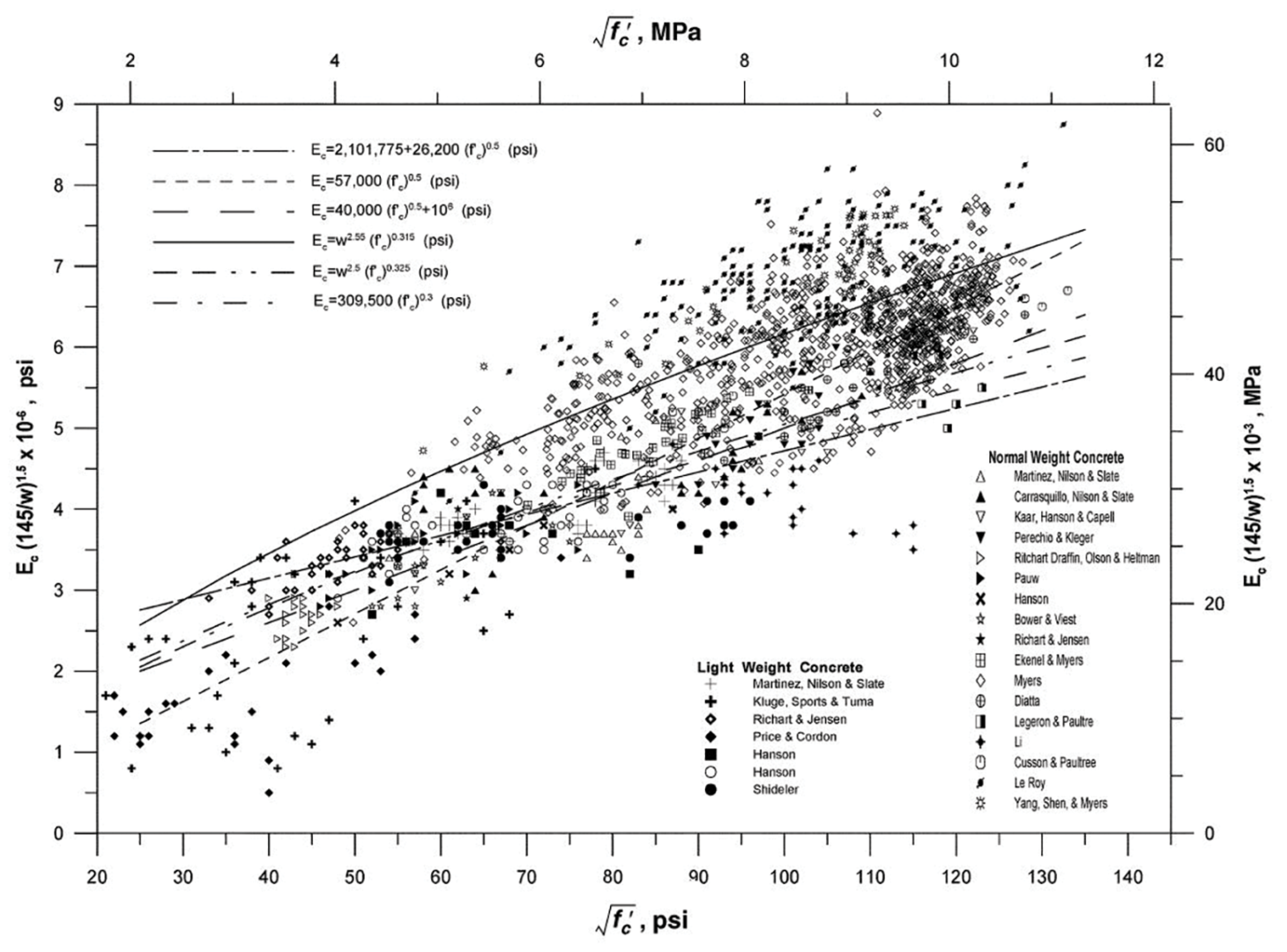
lower- and higher-strength concrete data (adapted from Myers and Yang (2004))
The following are offered regarding the uncertainty in ECONC assessment using the ACI relationship (Eq. 2):
- Hayes & Simmonds (2002) conclude that Eq. 2 may not always provide reasonable values for ECONC when converting strains to internal forces.
- Eq. 2 is based on regression through scattered data and is just one of many potential formulas among which to choose (Figure 1).
- Eq. 2 is based on the definition of ECONC as the slope of the line drawn from a stress of zero to a compressive stress of 0.45f’c. ECONC may vary, and therefore, the uncertainty associated with Eq. 2 may increase at stress levels other than 0.45f’c.
- The value of ECONC is more dependent on the unit weight of concrete, and the test method used to determine it, than on the concrete compressive strength (Pauw 1960). Eq. 2 implies that for an increase in concrete unit weight from 140 to 155 pounds per cubic foot (pcf), ECONC increases by over 16 per cent.
- Other researchers (Ahmad & Shah 1985, Freedman 1971) have concluded, and ACI 318-107 reports, that Eq. 2 predicts ECONC within ±20 per cent.
- ECONC is sensitive to the elastic modulus of the aggregate (ACI 318-14, 2014). This is not accounted for in Eq. 2.
- f’c determined from concrete cylinders in the laboratory may not reflect the strength of the mass concrete in the pile. Hayes & Simmonds (2002) state that it is generally acknowledged that ECONC correlates well to the 0.5 power of the compressive strength of the mass concrete in the pile. Studies by Khan et al. (1995) suggest that normal test cylinder curing methods result in values of laboratory-determined f’c that are significantly lower than the compressive strength of the mass concrete in the pile.
- Komurka and Robertson (2020) offer evidence that ECONC may be a function of depth/elevation within a pile, even for piles with constant cross-sections such as concrete-filled pipe piles (perhaps the fluid pressure to which concrete is subjected during curing affects the concrete’s final unit weight and modulus).
- ECONC is not constant over the strain range imposed by most static loading tests, as implied by Eq. 2, but decreases with increasing strain (Fellenius 1989). Komurka and Robertson (2020) demonstrated that ECONC can decrease by as much as 18 per cent over the strain range imposed during a static load test.
- Eq. 2 is better suited for concrete than grout. A modification factor, ʎ, ranging from 0.75 to one, can be applied to the square root of f’c in Eq. 2 based on the composition of aggregate in a grout mixture (ACI 2014), as it is generally understood that EGROUT is less than that of concrete for an equivalent axial compressive strength (Brown et al., 2007; Hassan et al., 1998). Additional strength modifiers to f’c may be required based on the grout sample size tested, as the strength requirement for tests performed on grout cubes is typically 10 per cent higher than that of cylinders (Brown et al., 2007). However, limited studies are available for reliably correlating f’c to EGROUT, nor are alternative methods for determining strain-dependent moduli of grout and concrete routinely implemented.
The I.R. method
Inspection of Equation 1 (Eq. 1) indicates that knowledge of the individual values of E and A is not strictly required; only determination of their product, EA, is required.
The I.R. method relates changes in test load to changes in strain to determine a direct relationship between internal force and strain, at interpretable strain gauge levels (discussed subsequently). The key to the I.R. method is the premise that after a pile’s shaft resistance is fully mobilized between a strain gauge level and the test load source, subsequent incremental increases in test load (∆Q) result in incremental increases in internal force (∆F) equal to ∆Q, and proportional strain increases (∆ε), at that level.
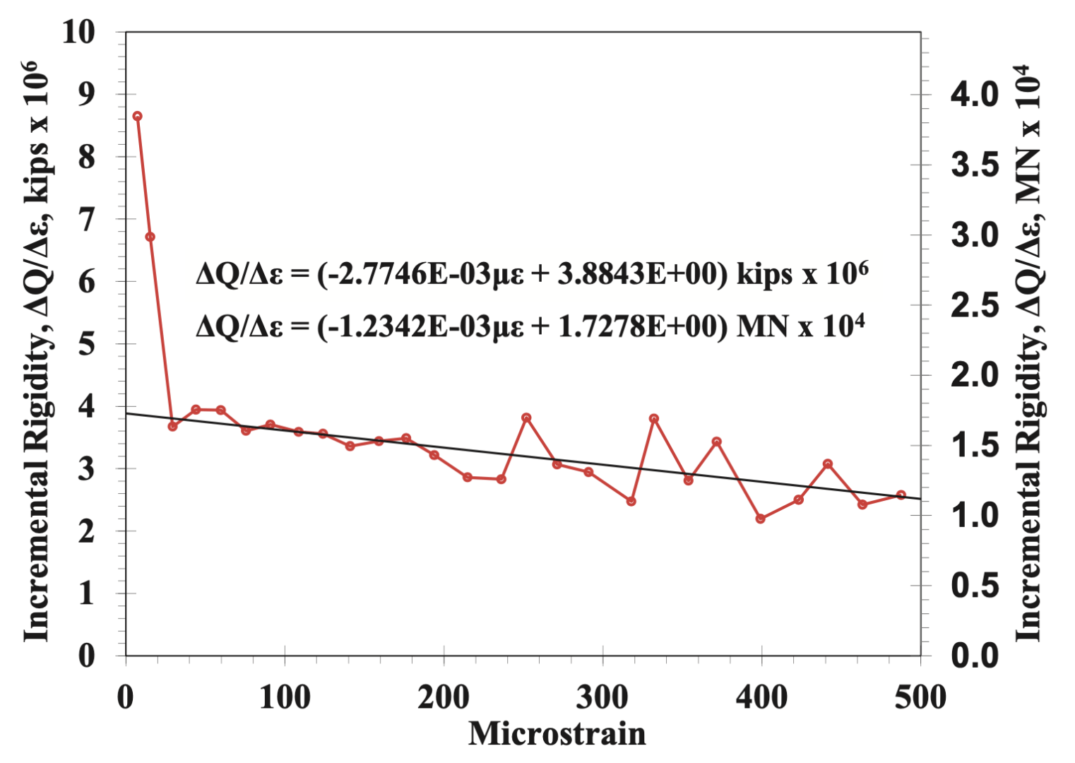
Plotting ∆Q/∆ε against strain for an individual strain gauge level resolves into a virtually straight line after a pile’s shaft resistance is fully mobilized between a strain gauge level and the test load source, sloping from larger to smaller I.R.s with increasing strain (Figure 2) for piles containing concrete or grout (cementitious materials), since the elastic modulus of cementitious materials is strain-dependent.
Rearranging Eq. 1 results in:
F/ε = EA = Rigidity of Composite Pile Material
Equation 3
Working with ∆Q (since this is measured during a static load test), and recognizing that after the shaft resistance between a strain gauge level and the load source is fully mobilized ∆Q = ∆F (i.e., changes in test load equal changes in internal force at that strain gauge level), the I.R. plot resolves to linear and the equation for the I.R. line in Figure 2 is:
Incremental Rigidity of Composite Pile
Material = (dQ/dε) = (dF/dε) = aε + b
Equation 4
Which can be integrated with respect to strain to:
Internal Force in the Pile = F = 0.5aε2 + bε
Equation 5
Since with zero internal force the strain should be zero, the integration constant is set equal to zero in Equation 5 (Eq. 5). Inspection of Eq. 5 indicates that, using the I.R. method, internal forces in a pile at interpretable strain gauge levels can be determined using only strain measurements, without knowledge of separate values for elastic modulus or cross-sectional area.
Obviously, this is of special benefit for non-uniform piles. However, even for apparently “uniform” piles, which contain a cementitious component (e.g., concrete-filled pipe piles, pre-stressed concrete piles, cased grouted piles), it is recommended that the I.R. method be applied, and potentially different relationships be used, at individual strain gauge levels. This is because concrete and grout are not uniform materials. They may appear to be, and are often treated as such, but they are not.
Some judgment must be applied in deciding which strain gauge levels provide interpretable results, and which do not. Since I.R. method application depends on fully mobilizing shaft resistance between the load source and the strain gauge level, levels closer to the load source are more likely to be interpretable than levels further from the load source. Statics show that to mobilize shaft resistance fully “upstream” (closer to the load source) of a strain gauge level, there must be at least that much resistance “downstream” (farther from the load source) of a strain gauge level. Accordingly, the I.R. method cannot be applied to strain gauge levels downstream from a pile’s resistance balance point (the resistance balance point being where upstream resistance equals downstream resistance).
It should be recognized that with the I.R. method, strain gauge levels are being used to characterize both: a pile’s structural properties (rigidities and back-calculated elastic moduli) and geotechnical load-transfer response. Accordingly, to address the structural characterization component of their purposes, sufficient strain gauge levels should be located upstream from the pile’s resistance balance point, even where the adjacent geomaterials’ resistance may not be of particular interest (owing to low strength, scour, liquefaction, future excavation, etc.).
At strain gauge levels which yield interpretable I.R. relationships, the initial rigidity, steel elastic modulus and relative cross-sectional areas of cementitious material and steel can be used to back-calculate an initial cementitious material modulus by the following relationship:
(ECONC)INITIAL = ((EA)INITIAL – ESTEELASTEEL)) / ACONC
Equation 6
At strain gauge levels which yield non-interpretable I.R. relationships, such as back-calculated initial cementitious material, moduli can be used to determine initial rigidity by the following relationship:
(EA)INITIAL = ESTEELASTEEL + (ECONC)INITIALACONC
Equation 7
(EA)INITIAL is the “b” parameter in Equations 4 and 5. To calculate internal force at non-interpretable strain gauge levels, a reasonable strain-dependent rigidity slope (the “a” parameter in Equations 4 and 5) is selected based on results from interpretable strain gauge levels.
Inspection of Equations 6 and 7 indicates the importance of determining (as best one can) the cross-sectional areas of steel and cementitious material at all strain gauge levels. Although this information may not be required at interpretable strain gauge levels, it is used at interpretable strain gauge levels to back-calculate parameters which are applied to non-interpretable strain gauge levels.
Required strain magnitude
For both compression and tension tests, the maximum internal force, which can be developed at a strain gauge level, is equal to the sum of the static resistance downstream from the test load. For a given internal force, a foundation with a higher rigidity will exhibit less strain than a foundation with a lower rigidity.
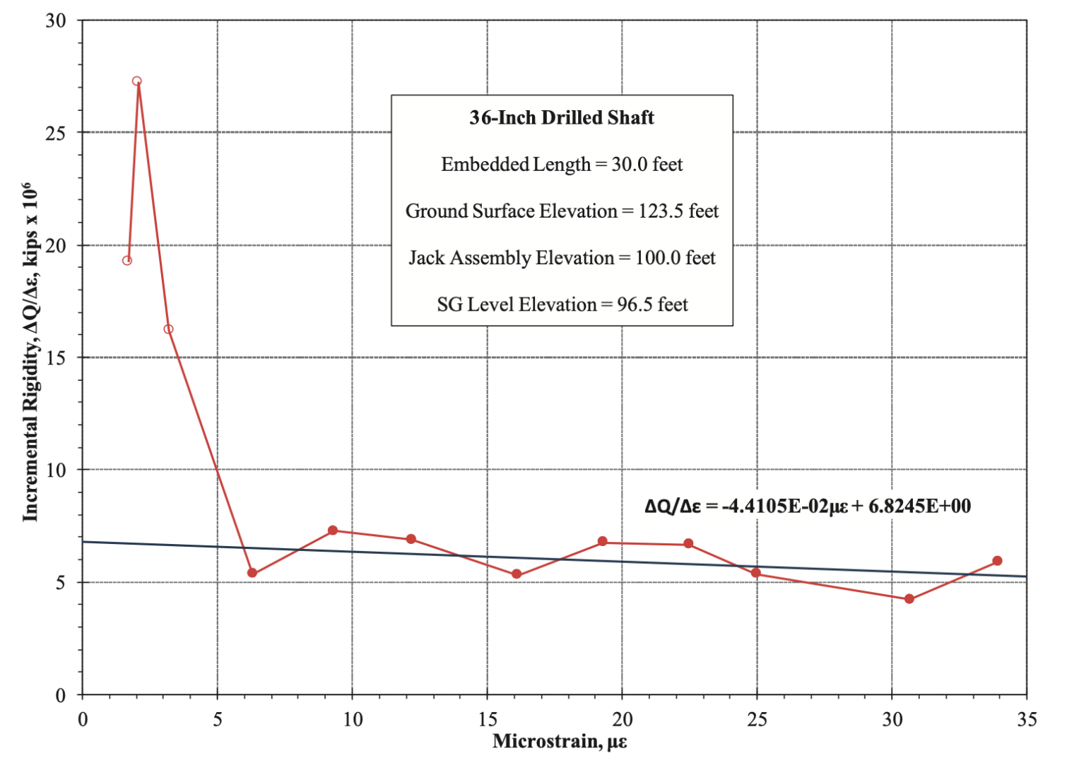
The I.R. plot for a strain gauge level located relatively near the test load, in a foundation with a large rigidity value relative to the internal forces produced during a static load test, may resolve into a linear response at relatively small strains. Figure 3 presents an I.R. plot from a bi-directional static load test (BDSLT) performed on a 36-inch-diameter (914-millimetre-diameter) drilled shaft. The strain gauge level presented was located 3.5 feet (1.1 metres) from the jack assembly’s lower bearing plate.
The soil surrounding the shaft between the lower bearing plate (i.e., the test load) and the strain gauge level consisted of soft clay. Applied load increments were approximately 20 kips (4.4 kilonewtons). The shaft resistance in this foundation segment was mobilized fairly early in the test, as evidenced by the relatively small number of load increments applied (three) before the I.R. plot exhibits linear response.
This, in conjunction with the foundation’s rigidity, accounts for the I.R. plot, exhibits a linear response at relatively small strains resulting from the internal forces achieved during the test after mobilization of the shaft resistance between the test load location and the strain gauge level.
Variable rigidities in an apparently uniform pile
One benefit of the I.R. method is that it can be applied to each individual strain gauge level to determine specific I.R. relationships for each level. For comparison purposes, it is recommended that I.R. relationships for all strain gauge levels in a static load test pile be presented on one plot. In some cases, it may be that I.R. relationships among various strain gauge levels are similar enough that a composite best-fit relationship derived from multiple strain gauge levels is appropriate.
In other cases, it may be appropriate that unique I.R. relationships be determined and applied on a level-by-level basis. Non-homogeneous cementitious material moduli within a drilled deep foundation have been identified by others (Hong et al. 2019).
However, this can be true even for what might be considered a uniform pile, such as closed-end concreted-in-place (CIP) piles or pre-cast concrete piles. Even in apparently uniform piles, cementitious material modulus (both its initial [zero-strain] value and its strain-dependency) can vary by location along the pile length. In this context, “uniform” refers to piles with a total cross-sectional area, and/or the respective areas of steel and cementitious material, that is constant by location within the pile.
Variable rigidity in what would normally be considered a uniform pile is demonstrated in the following example. The head-down static load test pile is an 18-inch-diameter (457-millimetre-diameter) closed-end CIP pipe pile, having an embedded length of 175 feet (53.3 metres), and 15 strain gauge levels approximately evenly spaced along its embedded length (including one at the ground surface).
The 15 strain gauge levels were numbered SG 1 through SG 15 consecutively from the ground surface to just above the pile toe. Table 1 presents the measured strains from the 15 SG levels at the maximum applied load. Inspection of Table 1 indicates that four strain gauge levels measured strains greater than a strain gauge level above them (underlined values). In a truly uniform pile (one with uniform rigidity), this is physically impossible.
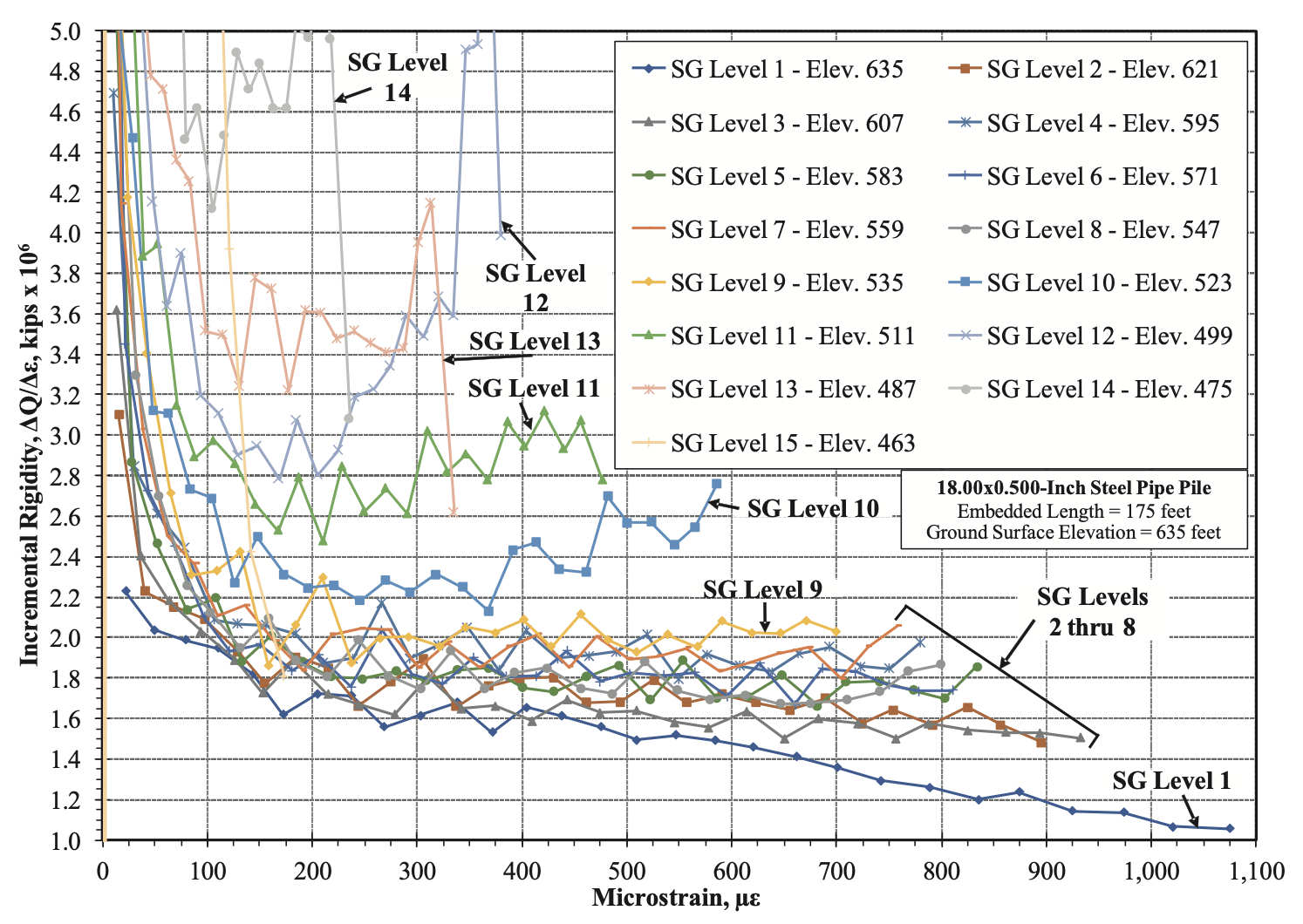
Conventional practice might perceive these readings in a CIP pile as suspect and ignore the results from these strain gauge levels, diminishing the effectiveness and value of the instrumentation program. In fact, while performing the test, the engineer noticed the apparent unreasonableness of these values and lamented the seemingly high gauge mortality rate. Figure 4 presents I.R. plots for all strain gauge levels in the test pile.
Inspection of Figure 4 indicates that, as is commonly the case for a CIP pipe pile, SG Level 1 located at the ground surface exhibited a different I.R. relationship than other strain gauge levels. By inspection, and evidenced by their positive slopes, it is apparent that SG Level 9 and all levels below it are affected by pile base/toe displacement, and therefore, are non-interpretable.
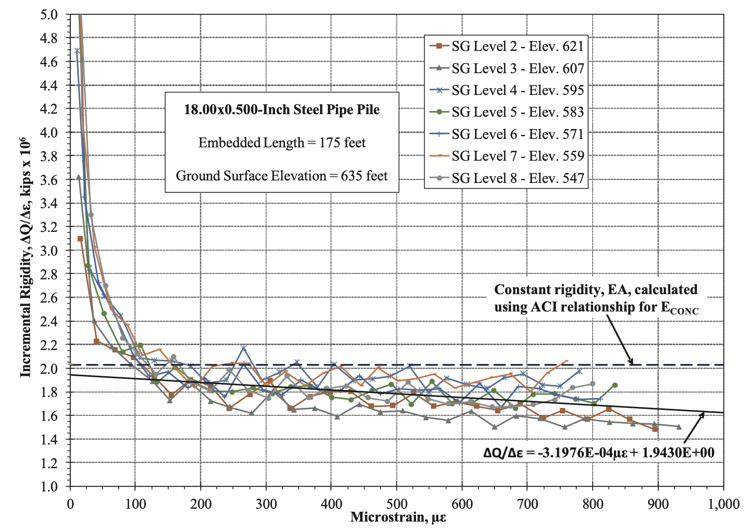
To provide comparison to the more conventional approach of estimating concrete modulus individually (as opposed to determining rigidity, EA), ECONC was estimated using the ACI relationship presented in Eq. 2. The average compressive strength of three concrete cylinders tested the day before the static load test was 5,327 pounds per square inch (36,728 kilopascals).
Assuming a concrete unit weight of 150 pounds per cubic foot (2,403 kilonewton centimetres), the ACI relationship yields a calculated concrete elastic modulus value of 4,424×103 psi (30,502×103 kilopascals) and a corresponding calculated pile rigidly of 2.03×10⁶ kips (9.03×10⁶ kilonewtons).
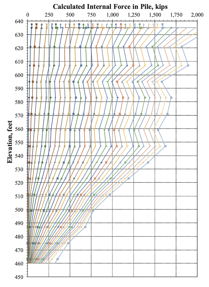
Since the strain-dependency of ECONC is not accounted for in Eq. 2, a pile’s rigidity so-determined plots as a horizontal line on an I.R. plot (Figure 5). The internal force profiles calculated by applying the constant rigidity value determined from ECONC based on the ACI relationship to all strain gauge levels is presented in Figure 6. To illustrate the effect of using a single I.R. relationship determined from the interpretable strain gauge levels and applying it to all strain gauge levels, Figure 5 presents the I.R. relationships for SG Levels 2 through 8, and the combined best-fit line through the data points.
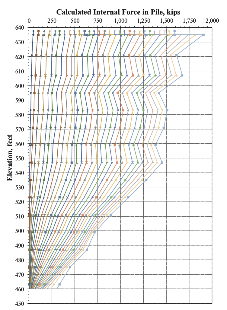
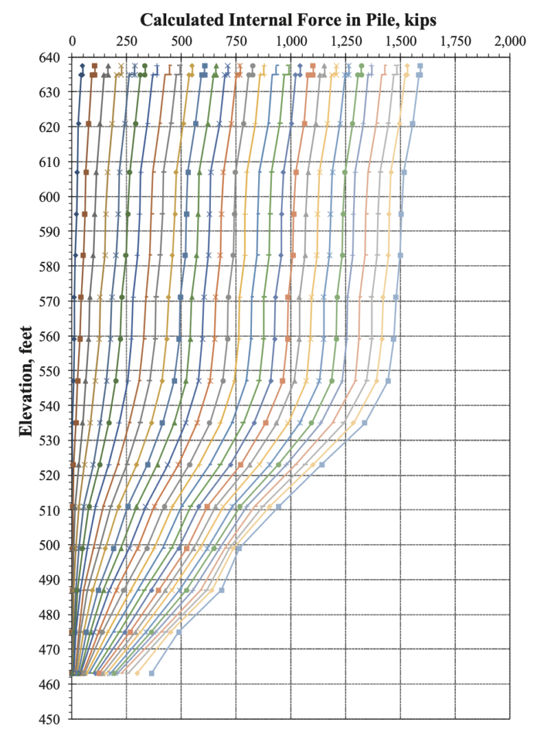
Figure 7 presents the internal force profiles calculated using the single best-fit strain-dependent I.R. relationship (Figure 5) applied to all strain gauge levels. Internal forces calculated using the constant (not strain-dependent) rigidity value determined using ECONC from the ACI relationship (Figure 6) exceed those calculated using the I.R. plots’ single best-fit trend line (Figure 7) by 15 per cent at the maximum strain measured during the static load test.
Inspection of Figures 6 and 7 confirms the indication of physically impossible internal force profiles, confirming that the test pile is indeed non-uniform and that use of either of the single I.R. relationship presented in Figure 5 is inappropriate.
Since the total cross-sectional area and the relative areas of steel and concrete in the CIP pipe pile were the same at each strain gauge level, and the modulus of steel can be considered constant at all locations and over the strain ranges imposed during the load test, the concrete modulus at the associated strain gauge levels must have varied by location within the pile.
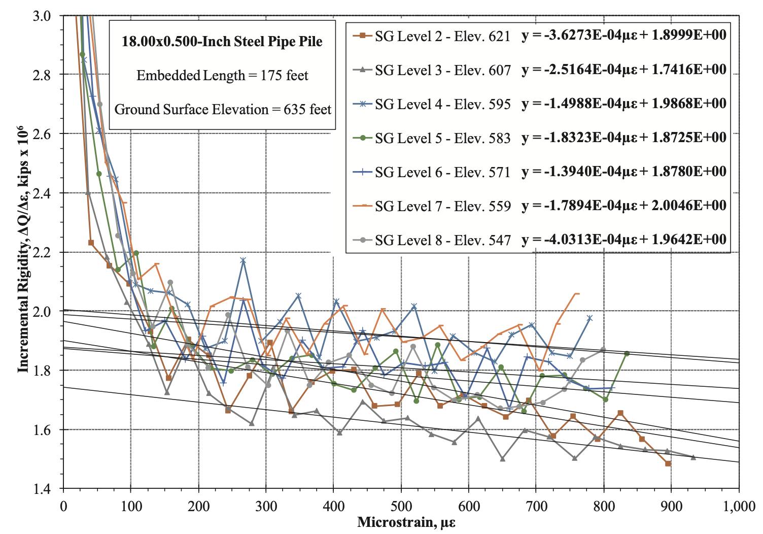
Figure 8 presents the I.R. relationships for SG Levels 2 through 8 plotted to a larger scale for clarity, with
best-fit lines through each individual I.R. relationship. Inspection of Figure 8 indicates that the individual I.R. relationships differ slightly from one another. Differences in initial (zero-strain) I.R. values, and therefore, initial concrete modulus values, determined from these seven strain gauge levels, vary by up to 15 per cent.
Figure 9 presents the internal force profiles determined from using the individual strain-dependent I.R. relationships (Figure 8). Inspection of Figure 9 indicates that the internal force profiles now appear reasonable, making physical sense in that all internal forces consistently decrease with depth (downstream from one another).

Test protocol
Implementing a number of static load test and data reduction protocols aids in improving I.R. method analyses (it is assumed that since numerous strain gauge readings are being obtained from multiple strain gauge levels, a datalogger is being used):
- Strain gauges should be located a minimum of two pile diameters from the load application and one diameter from the pile toe/base. For sister-bar strainmeters, this dimension ideally refers to the end of the sister bar, not to the centreline of the strainmeter.
- Consider an increased frequency of strain gauge levels near the test load.
- Avoid unload/reload cycles (Fellenius 2019, Siegel 2010). Cycling the load induces unrecoverable internal compressive load that varies non-uniformly along the pile length; shaft resistance distribution and direction will vary with depth and make strain gauge data interpretation difficult (Siegel 2010).
- Apply equal load increments, target a minimum of 20 increments.
- Hold each applied load as constant as possible. If the test is controlled by monitoring jack pressure, use a digital pressure gauge.
- Use equal hold times for each applied load increment.
- Longer applied-load hold times are better than shorter ones; suggest eight to 10 minutes minimum. Longer hold times provide more time for internal forces to “migrate” to the lower portions of a test pile, and for strains to stabilize (especially important for long friction piles), and they provide more pressure and strain data points to average for a given applied load increment.
- Record jack pressures using a pressure transducer and load cell readings (if used), using the same datalogger that is reading the strain gauges, so that pressure/load and strain readings occur at the same time and can be accurately related in time to each other.
- Use relatively short datalogger reading intervals, on the order of 30 seconds or less.
- When selecting values of applied load and measured strain for a given load increment, as opposed to selecting a single value from the last recorded row of datalogger data, use the average of representative load and strain readings over the hold time. Using average values can make the I.R. plots more interpretable (Komurka and Robertson, 2020).
The I.R. method offers many advantages over more conventional approaches to converting measured strains to calculated internal forces, and when properly applied, can enhance the implementation and interpretation of load-transfer data in static load tests.
Van E. Komurka is a senior engineer with GRL Engineers, Inc. who specializes in static load test services related to design, instrumentation, data reduction and interpretation, with special expertise in strain gauge data reduction. He can be reached at vkomurka@grlengineers.com (comments, feedback and discussion are encouraged).
Further information on the I.R. method, its applications, advantages and limitations, and illustrative case histories are detailed in two technical papers which can be found on GRL’s website at www.grlengineers.com/reference-papers/, filter by author: Komurka.
This article was previously published in PileDriver magazine and is reprinted here with permission.