Depth
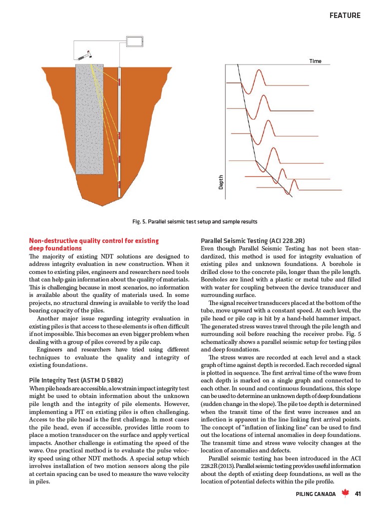
Fig. 5. Parallel seismic test setup and sample results
Non-destructive quality control for existing
deep foundations
The majority of existing NDT solutions are designed to
address integrity evaluation in new construction. When it
comes to existing piles, engineers and researchers need tools
that can help gain information about the quality of materials.
This is challenging because in most scenarios, no information
is available about the quality of materials used. In some
projects, no structural drawing is available to verify the load
bearing capacity of the piles.
Another major issue regarding integrity evaluation in
existing piles is that access to these elements is often difficult
if not impossible. This becomes an even bigger problem when
dealing with a group of piles covered by a pile cap.
Engineers and researchers have tried using different
techniques to evaluate the quality and integrity of
existing foundations.
Pile Integrity Test (ASTM D 5882)
When pile heads are accessible, a low strain impact integrity test
might be used to obtain information about the unknown
pile length and the integrity of pile elements. However,
implementing a PIT on existing piles is often challenging.
Access to the pile head is the first challenge. In most cases
the pile head, even if accessible, provides little room to
place a motion transducer on the surface and apply vertical
impacts. Another challenge is estimating the speed of the
wave. One practical method is to evaluate the pulse velocity
speed using other NDT methods. A special setup which
involves installation of two motion sensors along the pile
at certain spacing can be used to measure the wave velocity
in piles.
FEATURE
Time
Parallel Seismic Testing (ACI 228.2R)
Even though Parallel Seismic Testing has not been standardized,
this method is used for integrity evaluation of
existing piles and unknown foundations. A borehole is
drilled close to the concrete pile, longer than the pile length.
Boreholes are lined with a plastic or metal tube and filled
with water for coupling between the device transducer and
surrounding surface.
The signal receiver transducers placed at the bottom of the
tube, move upward with a constant speed. At each level, the
pile head or pile cap is hit by a hand-held hammer impact.
The generated stress waves travel through the pile length and
surrounding soil before reaching the receiver probe. Fig. 5
schematically shows a parallel seismic setup for testing piles
and deep foundations.
The stress waves are recorded at each level and a stack
graph of time against depth is recorded. Each recorded signal
is plotted in sequence. The first arrival time of the wave from
each depth is marked on a single graph and connected to
each other. In sound and continuous foundations, this slope
can be used to determine an unknown depth of deep foundations
(sudden change in the slope). The pile toe depth is determined
when the transit time of the first wave increases and an
inflection is apparent in the line linking first arrival points.
The concept of “inflation of linking line” can be used to find
out the locations of internal anomalies in deep foundations.
The transmit time and stress wave velocity changes at the
location of anomalies and defects.
Parallel seismic testing has been introduced in the ACI
228.2R (2013). Parallel seismic testing provides useful information
about the depth of existing deep foundations, as well as the
location of potential defects within the pile profile.
PILING CANADA 41